I2C devices
On the program side, machine.I2C makes the microcontroller the master of a real electrical I2C bus: it generates the clock on SCL and exchanges data on SDA (API). Peripherals provides three slave devices to connect to this bus. Their behaviour is always described by a Python script. Another MCU can also be the slave, with machine.I2CTarget (API, examples MultiMcu.I2c and MultiMcu.I2cIrq).
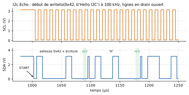
SCL and SDA lines of the I2c.Echo example: START, address byte, slave acknowledge, then first data byte. Figure labels are in French: « temps » = time, « adresse 0x42 + écriture » = address 0x42 + write.
Wiring
Two wires shared by every bus member, plus ground:
| Microcontroller | Each device |
|---|---|
SCL pin chosen by the program (e.g. GP4) |
SCL |
SDA pin chosen by the program (e.g. GP5) |
SDA |
GND |
GND |
from machine import Pin, I2C

i2c = I2C(0, scl=Pin(4), sda=Pin(5), freq=100000)
print(i2c.scan())                    # addresses present, e.g. [66]
i2c.writeto(0x42, b'Hello')
print(i2c.readfrom(0x42, 5))
The bus is open-drain: each member can only pull a line low or release it, and pull-up resistors bring the lines back up. At least one device on the bus must carry these resistors (usePullUp = true). I2C() does switch on the internal pull-ups of the microcontroller on SCL and SDA, as on the Pico, but 50 kΩ against the input capacitances of the devices is far too slow: a released line has no time to rise, and every transaction raises OSError(ETIMEDOUT), as on a board where the resistors were forgotten (I2c.NoPullUp example). The Grove display carries them by default, like the real module.
Any number of devices can share the two wires; each one only answers its own addresses (I2c.MultiDevice example).
Supplied devices
| Component | Address(es) | Default script | Role |
|---|---|---|---|
I2cGroveLcdRgb |
0x3E, 0x62 |
grove_lcd_rgb.py |
Grove - LCD RGB Backlight display, 16 × 2 characters, coloured backlight. Pull-ups enabled (usePullUp = true) |
I2cEchoDevice |
0x42 |
i2c_echo.py |
Test component: reads back to the master what it has just written |
I2cGenericDevice |
0x42, to be set |
i2c_generic.py |
Template: a bank of 16 registers, starting point for a new device |
Default scripts live in Resources/Scripts/Device/.
The Grove LCD RGB display
The real module carries two chips, hence two addresses for a single component; the script emulates them from their datasheets:
- JHD1313 (
0x3E, HD44780-compatible display controller): clear, home, write position, display on or off, shift. The display is off at power-up, like the real one: the driver must switch it on. - PCA9633 (
0x62, backlight driver): red, green, blue intensities.
The icon shows both lines and takes the backlight colour while replaying the result. valueOut returns (red, green, blue, display on), intensities from 0 to 255.
The I2c.GroveLcd example drives this display with an off-the-shelf MicroPython driver, run unmodified: driver_grove_lcd_rgb.py, placed next to the program that imports it.
Connectors
| Connector | Role |
|---|---|
SDA |
Bus data |
SCL |
Bus clock |
GND |
Ground, to connect to the microcontroller's |
valueIn[nIn] |
Model quantities passed to the script (v argument) |
valueOut[nOut] |
Quantities returned by the script (outputs()): the device becomes an actuator. May stay unconnected |
Parameters
Bus and behaviour (General tab)
| Parameter | Default | Group | Role |
|---|---|---|---|
addresses |
depends on the component | I2C bus | 7-bit address(es), as text: "0x42" or "0x3E, 0x62" (4 at most) |
usePullUp |
false (true for the Grove) |
I2C bus | Carry the SDA and SCL pull-up resistors to VOH. Several devices may carry them: they end up in parallel |
RPullUp |
4.7 kΩ | I2C bus | Value of each pull-up resistor |
scriptPath |
the component's script | Behaviour | .py file describing the device |
Inputs / outputs (Inputs / outputs tab)
| Parameter | Default | Role |
|---|---|---|
useValueInput |
false |
Take the quantities from the valueIn connector; otherwise, fixedValue |
nIn |
1 | Number of quantities received from the model (4 at most) |
fixedValue |
0 | Value used when valueIn is not used |
nOut |
1 (3 for the echo, 4 for the Grove) | Number of quantities returned by outputs() (4 at most) |
Electrical (Electrical tab)
| Parameter | Default | Role |
|---|---|---|
VOH |
3.3 V | Supply voltage of the pull-ups |
VIH, VIL |
2.0 V, 0.8 V | Reading thresholds of SDA and SCL |
ROut |
100 Ω | Resistance of the transistor pulling SDA low |
GOff |
1 nS | Leakage of the blocked transistor (line released) |
CIn |
10 pF | Input capacitance of each pin. With RPullUp, it sets the rise time of the edges (4.7 kΩ × 10 pF = 47 ns): increasing it shows the degraded edges of an overloaded bus |
Writing a device script
The script only sees transactions: no bits, no START/STOP, no acknowledges. Four functions, all optional:
registers = bytearray(16)
pointer = 0

def on_write(addr, data, t, v):     # the master has just written data (bytes, never empty)
    global pointer
    pointer = data[0] % 16
    for byte in data[1:]:
        registers[pointer] = byte
        pointer = (pointer + 1) % 16

def on_read(addr, t, v):            # the master starts reading
    return bytes(registers[pointer:])    # bytes, str, list of ints or int

def outputs():                      # read after each call -> valueOut
    return registers[0]

def lines():                        # read after each call -> two lines of text (displays)
    return ('line 1', 'line 2')
| Function | Called | Receives | Returns |
|---|---|---|---|
on_write(addr, data, t, v) |
at the end of an addressed write (STOP or repeated START) | addr: the address used; data: the bytes; t: simulated time; v: tuple of valueIn |
nothing |
on_read(addr, t, v) |
when the master starts a read | same, without data |
the bytes to send; on_read is called again if the master wants more, 0xFF if nothing |
outputs() |
after each handler | — | a number or a sequence, copied to valueOut |
lines() |
after each handler | — | two strings, for a display component |
addr lets a component with several addresses know which chip is being addressed. Same rules as for serial devices: a script loaded once per component, variables that persist from one call to the next, no waiting nor access to machine, print() in the log, simulation stopped on exception.
To create a new device: copy Resources/Scripts/Device/i2c_generic.py and select it in an I2cGenericDevice.
Variables to plot
| Variable | Contents |
|---|---|
dev.SDA.v, dev.SCL.v |
Line voltages (for a device named dev) |
dev.busy |
A transaction addressed to this device is in progress |
dev.sdaDriveLow |
The device pulls SDA low (acknowledge, bit at 0) |
dev.eventSeq |
Number of completed transactions |
« Chattering detected » message in the log
OpenModelica reports a burst of events within a single output step this way. It is harmless: the I2C sequence is event-driven. The message appears when the output interval (Interval) is large compared with the bus clock period; reducing it makes the message go away.
Examples
| Example | What it shows |
|---|---|
I2c.Echo |
Writing then reading back a frame; reading a register after a repeated START |
I2c.MultiDevice |
Three devices on a 400 kHz bus, found by scan() |
I2c.NoPullUp |
The same bus without external pull-up resistors: the internal pull-ups alone are too slow, OSError(ETIMEDOUT) |
I2c.GroveLcd |
Grove LCD RGB display driven by an off-the-shelf driver |
Weighing.KitchenScale |
Kitchen scale with a Grove display |