Weighing chain (HX711)
The Peripherals.Weighing sub-package models the measuring chain of an electronic scale, from the mass placed on it to the number read by the program. Its three components are written in pure Modelica (no C, no Python): a student can open them and read their equations.
flowchart LR
M["mass"] --> F["weight<br/>(Force)"] --> L["LoadCell"] --> B["WheatstoneBridge"] --> H["Hx711"] --> MCU["MCU"]| Link | Component | Input → output | With the defaults |
|---|---|---|---|
| Weight | Modelica.Mechanics.Translational.Sources.Force (standard library), preceded by a g_n gain |
mass → force | 1 kg → 9.81 N |
| Load cell | Weighing.LoadCell |
force → strain eps |
5 kg → 500 µm/m |
| Gauge bridge | Weighing.WheatstoneBridge |
eps → voltage S+ − S− |
500 µm/m → 1 mV/V |
| Converter | Weighing.Hx711 |
A+ − A− → 24-bit code |
1 kg at gain 128 → 429,497 |
Weighing.LoadCell: the load cell
A massless spring resting on a fixed point: the force applied to its flange deforms it, and the strain at the gauges follows the force instantly (eps = epsNom · F / FNom). It does not oscillate when a weight is placed, which is legitimate as long as the load varies slowly. The icon turns red on overload (more than 150 % of the capacity).
| Connector | Role |
|---|---|
flange |
Translational mechanical flange: where the load is applied (pan). A positive force deforms the load cell |
eps |
Output: strain at the gauges, to the bridge |
| Parameter | Default | Role |
|---|---|---|
capacity |
5 kg | Capacity: mass producing the nominal strain |
FNom |
capacity · g_n |
Nominal force (weight of the capacity) |
epsNom |
500·10⁻⁶ | Strain under the nominal force; with a gauge factor of 2, it gives 1 mV/V at the bridge output |
sNom |
0.2 mm | Deflection of the load cell under the nominal force |
Weighing.WheatstoneBridge: the gauge bridge
A full bridge of four gauges, two stretched and two compressed on the diagonals: R = R0 · (1 ± K · eps). Its output is E · K · eps, proportional to the excitation voltage E. Its internal diagram (Diagram tab) shows the four gauges.
| Connector | Role |
|---|---|
E_plus, E_minus |
Bridge supply (excitation), from E+ and E− of the HX711 |
S_plus, S_minus |
Bridge output, to A+ and A− of the HX711 |
eps |
Input: strain, from the load cell |
| Parameter | Default | Role |
|---|---|---|
R0 |
1 kΩ | Resistance of a gauge at rest |
K |
2 | Gauge factor: relative change in resistance per unit strain |
Weighing.Hx711: the converter
The HX711 powers the bridge, amplifies its voltage and converts it on 24 bits. The conversion is ratiometric: the code does not depend on the supply voltage.
The link with the microcontroller follows the datasheet: DOUT goes low when data is ready; each rising edge of PD_SCK shifts out one bit, most significant first; 25, 26 or 27 pulses select the gain of the next conversion (128, 32 or 64); PD_SCK held high for more than 60 µs puts the chip in power-down, which it leaves at gain 128.
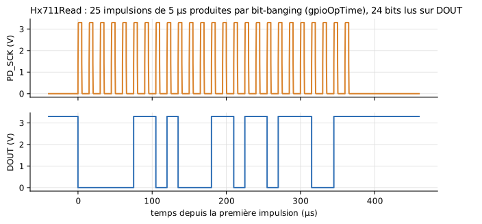
Figure labels are in French: « temps depuis la première impulsion » = time since the first pulse; the annotation reads "DOUT goes low: data ready, the driver's IRQ starts the read" and "bits read, most significant first: 0x068DB9 = 429,497 (1 kg, gain 128)".
The icon shows the gain and the last code, a cyan light when data is waiting to be read, an amber light in power-down.
| Connector | Role |
|---|---|
PD_SCK |
Serial clock and power-down control (SCK pin of the module), driven by the microcontroller |
DOUT |
Serial data (DT pin of the module), read by the microcontroller |
E_plus, E_minus |
Bridge excitation; E_minus is tied to the module ground |
A_plus, A_minus |
Channel A differential input, from the bridge output |
GND |
Ground, to connect to the microcontroller's |
| Parameter | Default | Group | Role |
|---|---|---|---|
rate |
10 Hz | Conversion | Conversion rate: 10 or 80 samples per second (RATE pin of the chip) |
AVDD |
4.3 V | Conversion | Bridge excitation voltage (module powered at 5 V) |
noiseLsb |
0 | Conversion | Conversion noise, standard deviation in LSB. 0: perfect, reproducible measurement |
seed |
711 | Conversion | Noise seed: same seed, same sequence of measurements |
tPowerDown |
60 µs | Timing | Time PD_SCK must stay high to enter power-down |
tUpdate |
10 µs | Timing | Time DOUT goes back up before each new sample, when the previous one was not read |
settlingConversions |
4 | Timing | Conversions discarded after power-up or leaving power-down (400 ms at 10 samples per second) |
VOH, VOL |
3.3 V, 0 V | Electrical | DOUT levels |
VIH, VIL |
2.0 V, 0.8 V | Electrical | PD_SCK reading thresholds |
ROut |
100 Ω | Electrical | Series resistance of the DOUT output |
Variables to plot (for an HX711 named hx): hx.code (last result), hx.gain, hx.pulses, hx.ready, hx.poweredDown, and the voltages hx.PD_SCK.v, hx.DOUT.v.
Reading the HX711 from the program
Robert Hammelrath's MicroPython driver hx711_gpio.py, supplied in Resources/Scripts/MCU/, is used as is, as on the board:
from machine import Pin
from hx711_gpio import HX711

hx = HX711(Pin(6, Pin.OUT), Pin(7, Pin.IN, pull=Pin.PULL_DOWN))   # PD_SCK, DOUT
hx.set_scale(429.497)       # counts per gram, measured with a known mass
hx.tare()                   # the empty pan becomes zero
print(hx.get_units())       # mass in grams
This driver generates the clock bit by bit, with no pause between two writes. This only works because each pin access costs MCU.gpioOpTime (5 µs by default): do not set gpioOpTime to 0 with an HX711. See The MCU block.
Examples
Weighing.Hx711Read: 1 kg on the scale, raw reading at gain 128, then at gain 64, power-down and wake-up. The codes read are the theoretical ones: 429,497, then 214,748.Weighing.KitchenScale: the complete scale. Grove LCD RGB display over I2C, HX711 with 25 LSB of noise, TARE button on an interrupt, a 200 g pan, then a 350 g bowl and 250 g of flour. The display shows "0 g", "350 g", "Tare...", "0 g", "250 g".
Long simulation
The complete scale takes about 45 s of computation for 7 simulated seconds: each character sent to the display is an I2C transaction, and the driver waits for each HX711 sample in 1 ms steps. That is the price of a faithful electrical simulation of two buses.
Limits
- Channel B (gain 32) is not wired: it reads 0 V.
- Each conversion is an instantaneous sample of the input, with no averaging nor settling time after a gain change.
- The
tUpdateduration is assumed: the datasheet does not give it.