Serial devices (UART)
On the program side, machine.UART produces a real electrical frame on two microcontroller pins (API). At the other end of the wire, Peripherals provides five serial devices: they decode what they receive, bit by bit, and reply with a real frame in turn.
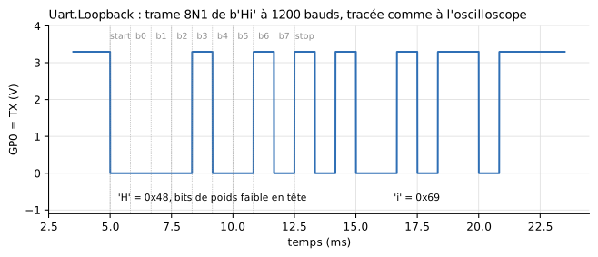
Voltage of the transmit pin (mcu.GP0.v) in the Uart.Loopback example: start bit at 0, 8 data bits (least significant first), stop bit at 1. Figure labels are in French: « temps » = time, « bits de poids faible en tête » = least significant bits first.
Wiring
Two crossed wires and a common ground, as on a real board:
| Microcontroller | Device | Direction |
|---|---|---|
TX pin chosen by the program (e.g. GP5) |
RX |
what the microcontroller sends |
RX pin chosen by the program (e.g. GP4) |
TX |
what the device replies |
GND |
GND |
common reference, required |
from machine import Pin, UART
import time

uart = UART(0, baudrate=1200, tx=Pin(5), rx=Pin(4))
uart.write(b'AT+TEMP\n')
time.sleep_ms(200)              # give the reply time to arrive
if uart.any():
    print(uart.readline())      # b'TEMP=21.5\r\n'
Reception does not wake the program up: it polls the link with any(), read() or readline().
Why GP4/GP5 in the examples?
These pins are on the right edge of the MCU icon, on the side where the device is placed: wires stay short. Any pair of GP0-GP7 works.
Supplied devices
They all share the same connectors and parameters; they only differ by their defaults and their icon.
| Component | What it does | Defaults that set it apart |
|---|---|---|
UartGenericDevice |
Device to be configured entirely in its parameter dialog | respondEnabled = true, empty table |
UartEchoDevice |
Sends back each received byte as is | echoEnabled = true |
UartTemperatureSensor |
Answers AT+TEMP with the value of its input, AT+ID with its identifier, and accepts a setpoint through SET <number> |
commandTable = "AT+TEMP=>TEMP={v1:.1f}\r\n|AT+ID=>SIM-TEMP-1\r\n|SET {o1}=>OK\r\n", responseDelay = 5 ms, useValueInput = true, fixedValue = 20, nOut = 1 |
UartGpsModule |
Sends a position frame every second on its own, without being asked | periodicEnabled = true, periodicTemplate = "$GPGLL,{v1:.4f},{v2:.4f},{v3:.1f}\r\n", useValueInput = true, nIn = 3 |
UartLcd20x2 |
2 × 20 character display: shows each received line on its icon, the previous one moving down to line 2 | never replies; behaviour fixed to Table |
Connectors
| Connector | Role |
|---|---|
TX |
Device transmit, to the microcontroller's RX pin |
RX |
Device receive, from the microcontroller's TX pin |
GND |
Ground, to connect to the microcontroller's |
valueIn[nIn] |
Model quantities the device inserts into its frames ({v1}…): a temperature, a position… Used if useValueInput = true |
valueOut[nOut] |
Quantities extracted from received frames ({o1}…): the device then becomes an actuator. May stay unconnected |
Parameters
Behaviour and link (General tab)
| Parameter | Default | Role |
|---|---|---|
behaviour |
Table |
Where the behaviour comes from: Table (command table, below) or Script (Python file) |
scriptPath |
the device's script | .py file describing the behaviour, in Script mode. Each supplied device has its own in Resources/Scripts/Device/ (generic.py, echo.py, temperature_sensor.py, gps.py), equivalent to its table |
baudrate |
1200 | Device baud rate. It must match the microcontroller's, otherwise received bytes are wrong, as on a real board |
terminator |
"\n" |
Character ending a received command (only the first character counts) |
tickPeriod |
0.1 s | Period of the minimal synchronisation point; a safety net, the default is fine |
Command table (Table tab, Table mode)
| Parameter | Default | Group | Role |
|---|---|---|---|
respondEnabled |
true |
Request / response | Answer the commands recognised by the table |
commandTable |
"" |
Request / response | Table "CMD=>REPLY|CMD=>REPLY" (format below) |
responseDelay |
2 ms | Request / response | Delay between the end of the received command and the start of the reply. Also used in Script mode |
echoEnabled |
false |
Request / response | Send back each received byte as is, as soon as it is decoded |
periodicEnabled |
false |
Periodic transmission | Send spontaneously, without being asked |
period |
1 s | Periodic transmission | Period of spontaneous sending (in Script mode: period of on_tick calls) |
periodicTemplate |
"" |
Periodic transmission | Frame sent periodically |
Inputs / outputs (Inputs / outputs tab)
| Parameter | Default | Role |
|---|---|---|
useValueInput |
false |
Take the quantities from the valueIn connector; otherwise, fixedValue |
nIn |
1 | Number of quantities received from the model (4 at most) |
fixedValue |
0 | Value used when valueIn is not used |
nOut |
1 | Number of quantities returned to the model on valueOut (4 at most) |
valueOutStart |
0 | Value of valueOut before any capture |
Electrical (Electrical tab)
| Parameter | Default | Role |
|---|---|---|
VOH, VOL |
3.3 V, 0 V | Levels sent on TX |
VIH, VIL |
2.0 V, 0.8 V | Reading thresholds of RX |
ROut |
100 Ω | Series resistance of the TX output |
RPullUp |
1 MΩ | RX pull-up to VOH: an unconnected input reads an idle level |
Describing the device with a table
A single string describes all commands: "CMD=>REPLY|CMD=>REPLY". The characters | and => are reserved. A command is recognised when the complete received line (without its terminator) is identical to it.
| Marker | Where | Meaning |
|---|---|---|
{v1}, {v2:.3f} |
in a reply or in periodicTemplate |
inserts valueIn[N], with an optional Python format |
{o1}, {o2} |
in a command | captures the number received at that place into valueOut[N] |
With this table, the program reads the temperature over the serial link and sends back a command over the same link. valueOut[1] passes it to the rest of the model: this is what the Uart.Regulation example does, a complete control loop through the two wires of the link alone.
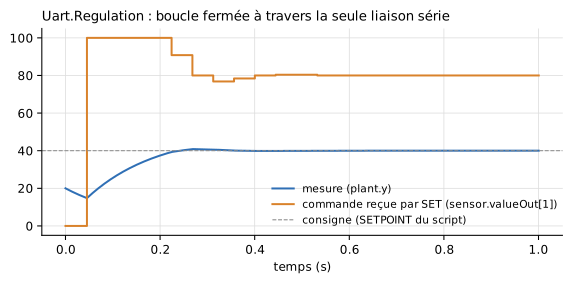
Legend: « mesure » = measurement, « commande reçue par SET » = command received through SET, « consigne » = setpoint.
Describing the device with a Python script
With behaviour = Script, the scriptPath file replaces the table. It defines up to three functions, all optional:
state = 'STOPPED'       # module variables: the device state,
readings = 0            # which persists from one call to the next

def on_receive(line, t, v):         # once per complete received line
    global state, readings
    if line == b'START':
        state = 'RUNNING'
        return b'OK\r\n'
    if line == b'READ' and state == 'RUNNING':
        readings += 1
        return 'VAL=%.2f N=%d\r\n' % (v[0], readings)
    return b'ERR\r\n'

def on_tick(t, v):                  # every `period` seconds, if defined
    return None

def outputs():                      # read after each call -> valueOut
    return (1.0 if state == 'RUNNING' else 0.0, readings)
| Function | Called | Receives | Returns |
|---|---|---|---|
on_receive(line, t, v) |
once per received line | line: bytes without the terminator; t: simulated time (s); v: tuple of the valueIn quantities |
bytes, str or None: reply sent after responseDelay |
on_tick(t, v) |
every period seconds; its mere presence enables periodic sending |
same | same, sent right away |
outputs() |
after each of the other two, and at load time | — | a number or a sequence, copied to valueOut |
Rules to know:
- The script is loaded once per device: two devices using the same file each have their own variables.
- Each line is delivered only once, even if the simulation re-evaluates the same instant several times: a state machine never replays its transitions.
- Functions must return without waiting: no
sleep()(responseDelaydelays a reply), nomachinenortime, which belong to the microcontroller. The file must be self-contained (no import of neighbouring files). print()goes to the log, prefixed with the device name. An exception stops the simulation.
Starting point: copy Resources/Scripts/Device/generic.py. Examples: Uart.EchoPy, Uart.GpsPy, Uart.StateMachinePy.
Variables to plot
| Variable | Contents |
|---|---|
dev.TX.v, dev.RX.v |
Voltages of both lines (for a device named dev) |
dev.txActive |
A frame is being sent |
dev.rxBusy |
A frame is being received |
dev.valueOut[N] |
Quantities captured by {oN} or returned by outputs() |
Looping the link back onto the microcontroller
To watch the frame of an MCU alone, without a device, connect its TX pin to its RX pin. Not with a plain wire: a direct connect() between two pins of the same MCU makes the driven voltage disappear from the results. Go through a 1 kΩ resistor, with a 1 nF capacitor from the RX pin to ground, as in the Uart.Loopback example; the frame is not distorted (time constant ≈ 1 µs, for 833 µs bits at 1200 baud).
Examples
| Example | What it shows |
|---|---|
Uart.Loopback |
Frame looped back onto the microcontroller, readable as on an oscilloscope |
Uart.EchoPy, Uart.Echo |
Dialogue with an echo device, in Script then Table mode |
Uart.Sensor |
Querying a temperature sensor, then sending a setpoint |
Uart.Regulation |
Closed control loop through the serial link |
Uart.GpsPy |
Spontaneous frames from a GPS module, counted by the program |
Uart.StateMachinePy |
State-machine device described in Python |
Uart.Lcd |
20x2 serial display; changing its baudrate shows the wrong characters of a mismatched baud rate |